I added the servo motors to control the crossover near the
site of the freight siding.
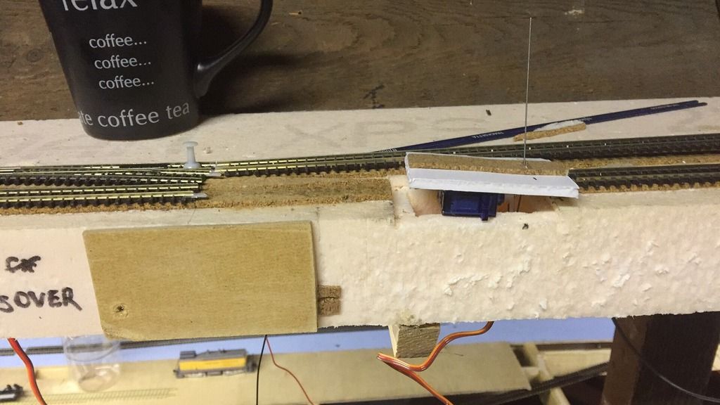
Servo Motor Installation Example
One placed on second crossover, second in progress. You can
see how the servo motor is mounted, and how this will throw the turnout once
the track is placed.
Crossover and Freight Spur Complete
Crossover in place, motors tested, surrounding track glued
in place. Won't get time to re-wire (short section between crossover and spur
has no power yet) so run testing will have to wait. Just need to power the spur
and the section of track immediately before it, as the original block has been
split. The section of mainline will allow small amounts of switching without
fouling the mainline crossover.
With this complete I left the glue to dry (resisting the
temptation to mess with it) and moved down the mainline the next crossover,
going the opposite direction.

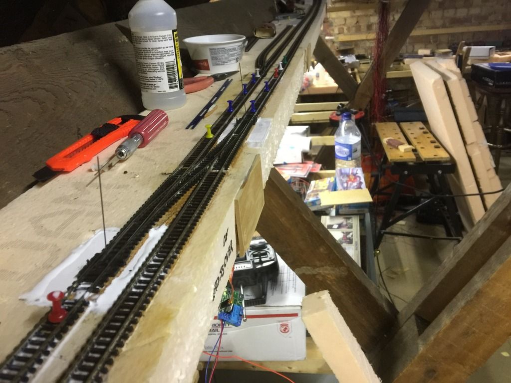
Powering Another Crossover
And on to the next crossover to get powered; you can see the
tools I use to cut the foam, the servo mounting pads, and the gaps where the
turnouts should be...
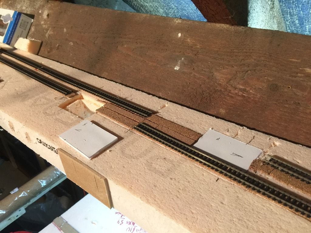
Opening the Mounting Pad Locations
Cuts made for the mounting pads; the combination of a saw
and sharp knife does wonders.

The Hole Detail
Detail of the hole for the mounting pad; you can see the lip
that supports the foam core board.
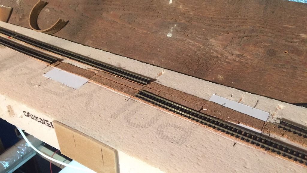
Roadbed Restored
Roadbed splices cut and glued. This cork sheet cut into
strips approximately as wide as the track ties.
By this point Imogen (the British have started naming winter
storms…) was putting too much cold wind through the attic, so I retreated
downstairs, since the glue was taking longer to dry. Hopefully in a couple of
weeks I’ll get this and the maybe even the next one done.